Monday, 19 February 2018

CONFIGURE VOICE MESSAGING AND PRESENCE

BACH NO:0066
FACULTY NAME: PRIYA MEM
STUDENT NAME: MOHAMMAD QADDAFI QURESHI


SUBJECT: JABBER CLIENT

Q.) Introduction to Client Configuration

Cisco Jabber can retrieve configuration settings from the following sources:
Service Profiles — You can configure some client settings in UC service profiles on Cisco Unified Communications Manager release 9 and later. When users launch the client, it discovers the Cisco Unified Communications Manager home cluster using a DNS SRV record and automatically retrieves the configuration from the UC service profile.
Applies to on-premises deployments only.
Phone Configuration You can set some client settings in the phone configuration on Cisco Unified Communications Manager release 9 and later. The client retrieves the settings from the phone configuration in addition to the configuration in the UC service profile.
Applies to on-premises deployments only.
Cisco Unified Communications Manager IM and Presence Service — You can enable instant messaging and presence capabilities and configure certain settings such as presence subscription requests.
In the Advanced settings window, if you select either Cisco IM & Presence or Cisco Communications Manager 8.x, the client retrieves UC services from Cisco Unified Presence or Cisco Unified Communications Manager IM and Presence Service. The client does not use service profiles or SSO discovery.


STEP FOR ADDING A CISCO JABBER CLIENT:
first choose Cisco unified client services framework
then write device name> (example in image is "CSF amine")
choose owner>user
owner user id> (example in image is "Qaddafi")
Primery phone> Qaddafi (end user Qaddafi as owner user)
  • add line, Assing to end user.

Monday, 29 January 2018

The Dynamic Host Configuration Protocol (DHCP) is a network management protocol used on TCP/IP networks whereby a DHCP server dynamically assigns an IP address and other network configuration parameters to each device on a network so they can communicate with other IP networks.[1] A DHCP server enables computers to request IP addresses and networking parameters automatically from the Internet service provider (ISP), reducing the need for a network administrator or a user to manually assign IP addresses to all network devices.[1] In the absence of a DHCP server, a computer or other device on the network needs to be manually assigned an IP address.
DHCP can be implemented on networks ranging in size from home networks to large campus networks and regional Internet service provider networks.[2] A router or a residential gateway can be enabled to act as a DHCP server. Most residential network routers receive a globally unique IP address within the ISP network. Within a local network, a DHCP server assigns a local IP address to each device connected to the network.

Tuesday, 16 January 2018

LINK STATE ROUTING PROTOCOLS

NAME:MOHAMMAD QADDAFI QURESHI
ROLL NO:JE.ENR-SW-1433
FACULTY NAME: PRIYA MEM
TOPIC NAME:LINK STATE ROUTING PROTOCOLS
Link State Routing Protocols
Link-state routing protocols are one of the two main classes of routing protocols used in packet switching networks for computer communications, the other being distance-vector routing protocols. Examples of link-state routing protocols include Open Shortest Path First (OSPF) and intermediate system to intermediate system (IS-IS).
The link-state protocol is performed by every switching node in the network (i.e., nodes that are prepared to forward packets; in the Internet, these are called routers). The basic concept of link-state routing is that every node constructs a map of the connectivity to the network, in the form of a graph, showing which nodes are connected to which other nodes. Each node then independently calculates the next best logical path from it to every possible destination in the network. Each collection of best paths will then form each node's routing table.
This contrasts with distance-vector routing protocols, which work by having each node share its routing table with its neighbours. In a link-state protocol the only information passed between nodes is connectivity related. Link-state algorithms are sometimes characterized informally as each router, "telling the world about its neighbours.
Distributing maps.
This description covers only the simplest configuration; i.e., one with no areas, so that all nodes have a map of the entire network. The hierarchical case is somewhat more complex; see the various protocol specifications.
As previously mentioned, the first main stage in the link-state algorithm is to give a map of the network to every node. This is done with several subsidiary steps.
Determining the neighbours of each node.
First, each node needs to determine what other ports it is connected to, over fully working links; it does this using a reachability protocol which it runs periodically and separately with each of its directly connected neighbours.
Distributing the information for the map
Next, each node periodically (and in case of connectivity changes) sends a short message, the link-state advertisement, which:
Identifies the node which is producing it.
Identifies all the other nodes (either routers or networks) to which it is directly connected.
Includes a sequence number, which increases every time the source node makes up a new version of the message.
This message is sent to all that node’s neighbors. As a necessary precursor, each node in the network remembers, for every one of its neighbors, the sequence number of the last link-state message which it received from that node. When a link-state advertisement is received at a node, the node looks up the sequence number it has stored for the source of that link-state message: if this message is newer (i.e., has a higher sequence number), it is saved, and a copy is sent in turn to each of that node's neighbors. This procedure rapidly gets a copy of the latest version of each node's link-state advertisement to every node in the network.
Networks running link state algorithms can also be segmented into hierarchies which limit the scope of route changes. These features mean that link state algorithms scale better to larger networks.
Creating the map
Finally, with the complete set of link-state advertisements (one from each node in the network) in hand, each node produces the graph for the map of the network. The algorithm iterates over the collection of link-state advertisements; for each one, it makes links on the map of the network, from the node which sent that message, to all the nodes which that message indicates are neighbors of the sending node.
No link is considered to have been correctly reported unless the two ends agree; i.e., if one node reports that it is connected to another, but the other node does not report that it is connected to the first, there is a problem, and the link is not included on the map.
Notes about this stage
The link-state message giving information about the neighbors is recomputed, and then flooded throughout the network, whenever there is a change in the connectivity between the node and its neighbors; e.g., when a link fails. Any such change will be detected by the reachability protocol which each node runs with its neighbors.
Calculating the routing table
As initially mentioned, the second main stage in the link-state algorithm is to produce routing tables, by inspecting the maps. This is again done with several steps.
Calculating the shortest paths
Each node independently runs an algorithm over the map to determine the shortest path from itself to every other node in the network; generally some variant of Dijkstra's algorithm is used. This is based around a link cost across each path which includes available bandwidth among other things.
A node maintains two data structures: a tree containing nodes which are "done", and a list of candidates. The algorithm starts with both structures empty; it then adds to the first one the node itself. The variant of a Greedy Algorithm then repetitively does the following:
All neighbour nodes which are directly connected to the node are just added to the tree (excepting any nodes which are already in either the tree or the candidate list). The rest are added to the second (candidate) list.
Each node in the candidate list is compared to each of the nodes already in the tree. The candidate node which is closest to any of the nodes already in the tree is itself moved into the tree and attached to the appropriate neighbor node. When a node is moved from the candidate list into the tree, it is removed from the candidate list and is not considered in subsequent iterations of the algorithm.
The above two steps are repeated as long as there are any nodes left in the candidate list. (When there are none, all the nodes in the network will have been added to the tree.) This procedure ends with the tree containing all the nodes in the network, with the node on which the algorithm is running as the root of the tree. The shortest path from that node to any other node is indicated by the list of nodes one traverses to get from the root of the tree, to the desired node in the tree.
Filling the routing table
With the shortest paths in hand, the next step is to fill in the routing table. For any given destination node, the best path for that destination is the node which is the first step from the root node, down the branch in the shortest-path tree which leads toward the desired destination node. To create the routing table, it is only necessary to walk the tree, remembering the identity of the node at the head of each branch, and filling in the routing table entry for each node one comes across with that identity.
Optimizations to the algorithm
The algorithm described above was made as simple as possible, to aid in ease of understanding. In practice, there are a number of optimizations which are used.
Partial Recomputation
Whenever a change in the connectivity map happens, it is necessary to recompute the shortest-path tree, and then recreate the routing table. Work by BBN Technologies[citation needed] discovered how to recompute only that part of the tree which could have been affected by a given change in the map. Also, the routing table would normally be filled in as the shortest-path tree is computed, instead of making it a separate operation.
Topology Reduction.
In some cases it is reasonable to reduce the number of nodes that generate LSA messages. For instance, a node that has only one connection to the network graph does not need to send LSA messages, as the information on its existence could be already included in the LSA message of its only neighbor. For this reason a topology reduction strategy can be applied, in which only a subset of the network nodes generate LSA messages. Two widely studied approaches for topology reduction are:
MultiPoint Relays that are at the base of the OLSR protocol but have also been proposed for OSPF[4]
Connected Dominating Sets that again have been proposed for OSPF[5]
Fisheye State Routing.
With FSR the LSA are sent with different TTL values in order to restrict their diffusion and limit the overhead due to control messages. The same concept is used also in the Hazy Sighted Link State Routing Protocol
Thursday, 4 January 2018

NETWORKING DEVICES


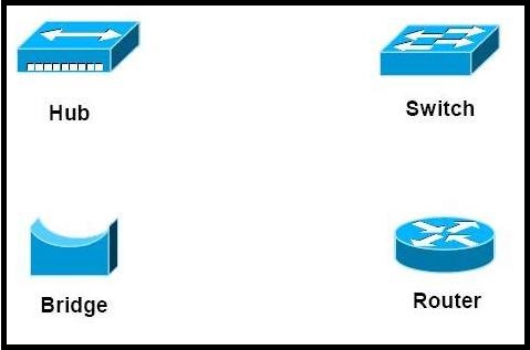
Network Devices (Hub, Repeater, Bridge, Switch, Router and Gateways)


symbols

1. Repeater – A repeater operates at the physical layer. Its job is to regenerate the signal over the same network before the signal becomes too weak or corrupted so as to extend the length to which the signal can be transmitted over the same network. An important point to be noted about repeaters is that they do no amplify the signal. When the signal becomes weak, they copy the signal bit by bit and regenerate it at the original strength. It is a 2 port device.

2. Hub –  A hub is basically a multiport repeater. A hub connects multiple wires coming from different branches, for example, the connector in star topology which connects different stations. Hubs cannot filter data, so data packets are sent to all connected devices.  In other words, collision domain of all hosts connected through Hub remains one.  Also, they do not have intelligence to find out best path for data packets which leads to inefficiencies and wastage.

3. Bridge – A bridge operates at data link layer. A bridge is a repeater, with add on functionality of filtering content by reading the MAC addresses of source and destination. It is also used for interconnecting two LANs working on the same protocol. It has a single input and single output port, thus making it a 2 port device.

4. Switch – A switch is a multi port bridge with a buffer and a design that can boost its efficiency(large number of  ports imply less traffic) and performance. Switch is data link layer device. Switch can perform error checking before forwarding data, that makes it very efficient as it does not forward packets that have errors and  forward good packets selectively to correct port only.  In other words, switch divides collision domain of hosts, but broadcast domain remains same.

5. Routers – A router is a device like a switch that routes data packets based on their IP addresses. Router is mainly a Network Layer device. Routers normally connect LANs and WANs together and have a dynamically updating routing table based on which they make decisions on routing the data packets. Router divide broadcast domains of hosts connected through it.
img1

6. Gateway – A gateway, as the name suggests, is a passage to connect two networks together that may work upon different networking models. They basically works as the messenger agents that take data from one system, interpret it, and transfer it to another system. Gateways are also called protocol converters and can operate at any network layer. Gateways are generally more complex than switch or router.

Why does DNS use UDP and not TCP?


DNS is an application layer protocol. All application layer protocols use one of the two transport layer protocols, UDP and TCP. TCP is reliable and UDP is not reliable. DNS is supposed to be reliable, but it uses UDP, why?

There are following interesting facts about TCP and UDP on transport layer that justify the above.
1) UDP is much faster. TCP is slow as it requires 3 way handshake. The load on DNS servers is also an important factor. DNS servers (since they use UDP) don’t have keep connections.
2) DNS requests are generally very small and fit well within UDP segments.
2) UDP is not reliable, but reliability can added on application layer. An application can use UDP and can be reliable by using timeout and resend at application layer.

  • Network Devices (Hub, Repeater, Bridge, Switch, Router and Gateways)
  • Simple Mail Transfer Protocol (SMTP)
  • DNS (Domain Name Server) | NetWorking.
  • LZW (Lempel–Ziv–Welch) Compression technique
  • What’s difference between http:// and https:// ?
  • Computer Network | Dynamic Host Configuration Protocol (DHCP)
  • Computer Network | Hamming Code
  • Network Neutrality | All you need to know
  • Computer Network | Fixed and Flooding Routing algorithms
  • Computer Network | Types of area networks – LAN, MAN and WAN
  • Computer Network | Circuit Switching VS Packet Switching

    CIRCUIT SWITCHINGPACKET SWITCHING
    In circuit switching there are 3 phases
    i) Connection Establishment.
    ii) Data Transfer.
    iii) Connection Released.
    In Packet switching directly data transfer takes place .
    In circuit switching, each data unit know the entire path address which is provided by the sourceIn Packet switching, each data unit just know the final destination address intermediate path is decided by the routers.
    In Circuit switching, data is processed at source system onlyIn Packet switching, data is processed at all intermediate node including source system.
    Delay between data units in circuit switching is uniform.Delay between data units in packet switching is not uniform.
    Resource reservation is the feature of circuit switching because path is fixed for data transmission.There is no resource reservation because bandwidth is shared among users.
    Circuit switching is more reliable.Packet switching is less reliable.
    Wastage of resources are more in Circuit SwitchingLess wastage of resources as compared to Circuit Switching

    Commonly asked Computer Networks Interview Questions | Set 1


    What are Unicasting, Anycasting, Multiccasting and Broadcasting?
    If the message is sent from a source to a single destination node, it is called Unicasting. This is typically done in networks.
    If the message is sent from a source to a any of the given destination nodes. This is used a lot in Content delivery Systems where we want to get content from any server.
    If the message is sent to some subset of other nodes, it is called Multicasting. Used in situation when there are multiple receivers of same data. Like video conferencing, updating something on CDN servers which have replica of same data.
    If the message is sent to all the nodes in a network it is called Broadcasting. This is typically used in Local networks, for examples DHCP and ARP use broadcasting.
    What are layers in OSI model?
    There are total 7 layers
    1. Physical Layer
    2. Data Link Layer
    3. Network Layer
    4. Transport Layer
    5. Session Layer
    6. Presentation Layer
    7. Application Layer
    What is Stop-and-Wait Protocol?
    In Stop and wait protocol, a sender after sending a frame waits for acknowledgement of the frame and sends the next frame only when acknowledgement of the frame has received.
    What is Piggybacking?
    Piggybacking is used in bi-directional data transmission in the network layer (OSI model). The idea is to improve efficiency piggy back acknowledgement (of the received data) on the data frame (to be sent) instead of sending a separate frame.
    Differences between Hub, Switch and Router?
    HubSwitchRouter
    Physical Layer DeviceData Link Layer DeviceNetwork Layer Device
    Simply repeats signal to all portsDoesn’t simply repeat, but filters content by MAC or LAN addressRoutes data based on IP address
    Connects devices within a single LANCan connect multiple sub-LANs within a single LANConnect multiple  LANS and WANS together.
    Collision domain of all hosts connected through Hub remains one. i.e., if signal sent by any two devices can collide.Switch divides collision domain, but broadcast domain of connected devices remains same.It divides both collision and broadcast domains,
    See network devices for more details.
    What happens when you type a URL in web browser?
    A URL may contain request to HTML, image file or any other type.
    1. If content of the typed URL is in cache and fresh, then display the content.
    2. Else find IP address for the domain so that a TCP connection can be setup. Browser does a DNS lookup.
    3. Browser needs to know IP address for a url, so that it can setup a TCP connection.  This is why browser needs DNS service.  Browser first looks for URL-IP mapping browser cache, then in OS cache. If all caches are empty, then it makes a recursive query to the local DNS server.   The local DNS server provides the IP address.
    4. Browser sets up a TCP connection using three way handshake.
    5. Browser sends a HTTP request.
    6. Server has a web server like Apache, IIS running that handles incoming HTTP request and sends a HTTP response.
    7. Browser receives the HTTP response and renders the content.
    What is DHCP, how does it work?
      1. The idea of DHCP (Dynamic Host Configuration Protocol) is to enable devices to get IP address without any manual configuration.
      2. The device sends a broadcast message saying “I am new here”
      3. The DHCP server sees the message and responds back to the device and typically allocates an IP address. All other devices on network ignore the message of new device as they are not DHCP server.
    In Wi Fi networks, Access Points generally work as a DHCP server.
    What is ARP, how does it work?
    ARP stands for Address Resolution Protocol. ARP is used to find LAN address from Network address. A node typically has destination IP to send a packet, the nodes needs link layer address to send a frame over local link. The ARP protocol helps here.
      1. The node sends a broadcast message to all nodes saying what is the MAC address of this IP address.
      2. Node with the provided IP address replies with the MAC address.
    Like DHCP, ARP is a discovery protocol, but unlike DHCP there is not server here.
    See this video for detailed explanation.
    Practice Quizzes for Networking

    Computer Networks | Longest Prefix Matching in Routers


    What is Forwarding?
    Forwarding is moving incoming packets to appropriate interface. Routers use forwarding table to decide which incoming packet should be forwarded to which next hop.
    What is IP prefix?
    IP prefix is a prefix of IP address. All computers on one network have same IP prefix. For example, in 192.24.0.0/18, 18 is length of prefix and prefix is first 18 bits of the address.
    How does forwarding work?
    Routers basically look at destination address’s IP prefix, searches the forwarding table for a match and forwards the packet to corresponding next hop in forwarding table.
    What happens if the prefixes overlap?
    Since prefixes might overlap (this is possible as classless addressing is used everywhere), an incoming IP’s prefix may match multiple IP entries in table.
    For example, consider the below forwarding table
    GATE CN1
    In above table, addresses from 192.24.12.0 to 192.24.15.255 overlap, i.e., match with both entries of the table.
    To handle above situation, routers use Longest Prefix Matching rule. The rule is to find the entry in table which has the longest prefix matching with incoming packet’s destination IP, and forward the packet to corresponding next hope.
    In the above example, all packets in overlapping range (192.24.12.0 to 192.24.15.255) are forwarded to next hop B as B has longer prefix (22 bits).
    longestprefix


    Example 1: Routers forward a packet using forwarding table entries. The network address of incoming packet may match multiple entries. How routers resolve this?
    (A) Forward it the the router whose entry matches with the longest prefix of incoming packet
    (B) Forward the packet to all routers whose network addresses match.
    (C) Discard the packet.
    (D) Forward it the the router whose entry matches with the longest suffix of incoming packet
    Answer: (A) The network addresses of different entries may overlap in forwarding table. Routers forward the incoming packet to the router which hash the longest prefix matching with the incoming packet.

    Example 2: Classless Inter-domain Routing (CIDR) receives a packet with address 131.23.151.76. The router’s routing table has the following entries: (GATE CS 2015)
    Prefix           Output Interface Identifier
    131.16.0.0/12              3
    131.28.0.0/14              5
    131.19.0.0/16              2
    131.22.0.0/15              1 
    The identifier of the output interface on which this packet will be forwarded is ______.
    Answer: “1”. We need to first find out matching table entries for incoming packet with address “131.23.151.76”. The address matches with two entries “131.16.0.0/12” and “131.22.0.0/15” (We found this by matching first 12 and 15 bits respectively).
    So should the packet go to interface 3 or 1? We use Longest Prefix Matching to decide among two. The most specific of the matching table entries is used as the interface. Since “131.22.0.0/15” is most specific, the packet goes to interface 1.

    Exercise
    Consider the following routing table of a router.
    GATE CN1
    Consider the following three IP addresses.
    GATE CN
    How are the packets with above three destination IP addresses are forwarded?
    (A) 1->D, 2->B, 3->B
    (B) 1->D, 2->B, 3->D
    (C) 1->B, 2->D, 3->D
    (D) 1->D, 2->D, 3->D
    Please write comments if you find anything incorrect, or you want to share more information about the topic discussed above


    STUDENT: MOHAMMAD QADDAFI QURESHI
    BACH NO:397
    PRIYA MEDUM
  • Tuesday, 2 January 2018

    WIRELESS NETWORKING